Augmented Shanahan: Extrapolation
 Click here to view.
This is the second part of a three-part writeup on my augmented Shanahan project. You may want to start with part one. For some background math, you may also want to read the post about my 5C Hackathon entry
From the detection and tracking algorithms, I was able to generate a 2D perspective transformation matrix that mapped coordinates on the wall to pixels in the image. In order to do 3D rendering, however, I needed a 3D transformation matrix. The algorithm I ended up using is based on this post on Stack Exchange, this gist on GitHub, and this Wikipedia page. I will attempt to describe how the algorithm works in the rest of this post.
A camera's view, in general, can be modeled with a pinhole camera model, which maps 3d points to points on a 2d plane by drawing a line from the point to a focal point, and then intersecting that line with the image plane.
 From http://homepages.inf.ed.ac.uk/
This can be calculated using a camera matrix, a 3 by 4 matrix that you can multiply with a 3D point and get a 2D image point in homogenous coordinates. The camera matrix is the product of two other matricies, the intrinsic parameters and the extrinsic parameters. The intrinsic parameters measure the focal length of the camera and other camera-specific measurements, and take the form
$$K = \begin{bmatrix}\alpha_u&s&u_0\\0&\alpha_v&v_0\\0&0&1\end{bmatrix}$$
where $\alpha_u$ and $\alpha_v$ are the focal length of the camera in terms of pixels in the x and y directions, respectively, $u_0$ and $v_0$ are the coordinates of the principal point, generally the center of the image, and $s$ is a skew factor.
The extrinsic parameters are a concatenation of the rotation matrix and the translation, taking the form
$$[R|t] = \begin{bmatrix} R_{11}&R_{12}&R_{13}&T_x\\R_{21}&R_{22}&R_{23}&T_y\\R_{31}&R_{32}&R_{33}&T_z \end{bmatrix}$$
where $R$ is an orthogonal matrix, and $T_x$, $T_y$, and $T_z$ give the position of the camera.
To find the coordinates of a given 3D point, we can compute the following product:
$$m = C\begin{bmatrix} X \\ Y \\ Z \\ 1 \end{bmatrix} = \begin{bmatrix}\alpha_u&s&u_0\\0&\alpha_v&v_0\\0&0&1\end{bmatrix}\begin{bmatrix} R_{11}&R_{12}&R_{13}&T_x\\R_{21}&R_{22}&R_{23}&T_y\\R_{31}&R_{32}&R_{33}&T_z \end{bmatrix}\begin{bmatrix} X \\ Y \\ Z \\ 1 \end{bmatrix}$$
which leaves us with a 2D vector in homogenous coordinates. If we knew the matrix $C$, we could render objects with the correct perspective. Unfortunately, we do not. However, we can compute a good estimate if we make a few assumptions.
For example, we know that, for a normal camera, the pixels are square, so $\alpha_u = \alpha_v = f$, the focal length. We know that $u_0$ and $v_0$ are the principal point, which is the center of the camera view and can be calculated from the width and height of the image. And we know that $s$ is 0, because the image is not skewed. Thus the only thing we do not know in the intrinsic matrix is $f$. We do not need perfect rendering, however, so I took a shortcut: I tried running the program with various values for $f$, and picked one that looked good. This might mean the augmented reality is slightly inaccurate for some device cameras, but it's better than nothing, and I didn't want to go through a complex camera calibration method for each user.
Using this guess of $f$, we know the intrinsic matrix. We still need to calculate the extrinsic parameters, however. To do this, notice what happens when we try to map a point with $z=0$ to an image point. By the rules of matrix multiplication, the entire third column of the matrix is nullified by the 0:
$$m = \begin{bmatrix}\alpha_u&s&u_0\\0&\alpha_v&v_0\\0&0&1\end{bmatrix}\begin{bmatrix} R_{11}&R_{12}&R_{13}&T_x\\R_{21}&R_{22}&R_{23}&T_y\\R_{31}&R_{32}&R_{33}&T_z \end{bmatrix}\begin{bmatrix} X \\ Y \\ 0 \\ 1 \end{bmatrix}$$ $$m = \begin{bmatrix}\alpha_u&s&u_0\\0&\alpha_v&v_0\\0&0&1\end{bmatrix}\begin{bmatrix} R_{11}&R_{12}&T_x\\R_{21}&R_{22}&T_y\\R_{31}&R_{32}&T_z \end{bmatrix}\begin{bmatrix} X \\ Y \\ 1 \end{bmatrix}$$
We can then multiply the intrinsic and modified extrinsic matricies together to make some 3 by 3 matrix $H$:
$$H = \begin{bmatrix}\alpha_u&s&u_0\\0&\alpha_v&v_0\\0&0&1\end{bmatrix}\begin{bmatrix} R_{11}&R_{12}&T_x\\R_{21}&R_{22}&T_y\\R_{31}&R_{32}&T_z \end{bmatrix} = K \begin{bmatrix} R_{11}&R_{12}&T_x\\R_{21}&R_{22}&T_y\\R_{31}&R_{32}&T_z \end{bmatrix}$$ $$m = H\begin{bmatrix} X \\ Y \\ 1 \end{bmatrix}$$
So $H$ is a 3 by 3 matrix that maps a 2d point on the $Z=0$ plane to a 2d point on the image plane. That's what our homography does! Thus H must be our homography matrix, which we know. And since we know the intrinsic matrix $K$, we can take its inverse and multiply it through to obtain
$$\begin{bmatrix} R_{11}&R_{12}&T_x\\R_{21}&R_{22}&T_y\\R_{31}&R_{32}&T_z \end{bmatrix} = K^{-1}H$$
Using this, we can solve for 3 of the 4 columns of the extrinsic parameters. But we still need one of the rotation columns. Luckily, we know another thing: since $R$ is an orthogonal matrix, each of the first three columns must be perpendicular unit vectors! So we can use the cross product to calculate the third vector, and thus complete our extrinsic matrix.
There is a slight problem here, in that the calculated homography does not necessarily match a valid 3D perspective transformation matrix exactly. It is possible that, due to detection error or the estimate of $f$ that the first two columns of $R$ are not quite perpendicular, and not quite the same length. We can, however, do our best by making at least one of the columns a unit vector, and then taking the cross product anyway. We can then use singular value decomposition to get the closest orthogonal matrix to the given matrix.
I don't fully understand how singular value decomposition works, but the result seems to be that a matrix is factored into a product of an initial rotation, a scaling, and then another rotation. The math.js library kindly enough provides this factorization. Since we don't want scaling for an orthogonal matrix, we can discard the scaling component and multiply the two rotations to get an orthogonal matrix close to the original matrix. Now we have estimated all parameters of the camera matrix, so we can multiply the estimated intrinsic matrix with our calculated extrinsic matrix and obtain the 3 by 4 camera matrix that we need.
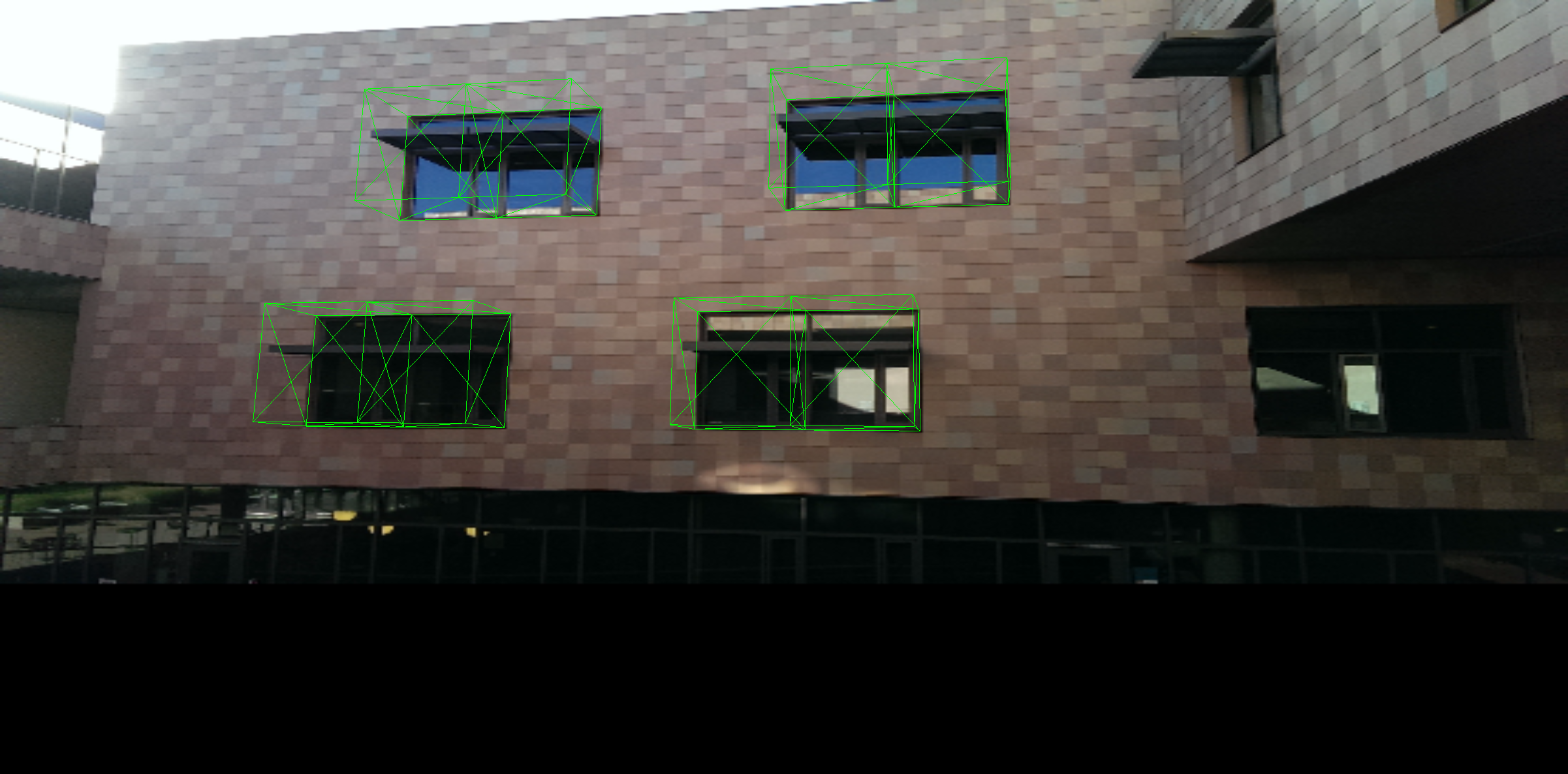
There is one more problem, however. If we use the closest orthogonal matrix that we calculated, we end up modifying the first two columns of the rotation matrix, which means the transformed coordinates no longer quite match up with the coordinates we get using the 2D transformation matrix, and thus the corners of the wall no longer match up either. My solution for this was to only take the third column of the orthogonal matrix, and keep the first two columns as calculated from the homography. That forces all points with $Z=0$ to match the calculated homography, keeping the rendering consistent.
Since three.js requires a 4x4 matrix for depth testing, I simply insert a 3rd column of [0 0 1 0] to preserve the Z coordinate. Then I can give that to three.js as a perspective matrix and it will happily render in 3d on top of the wall!
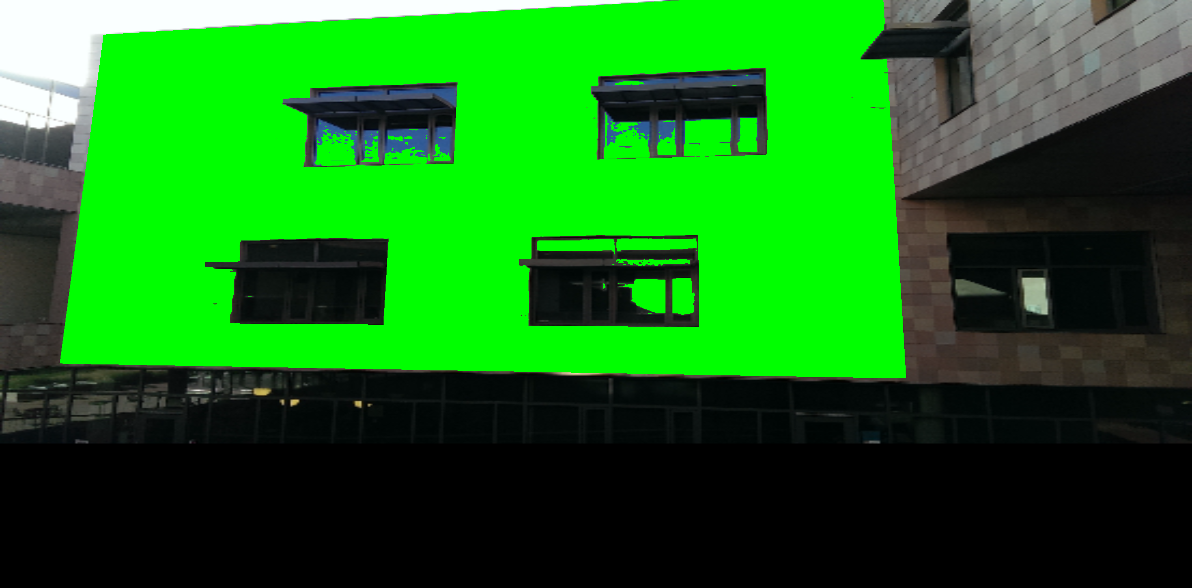
In order to make the effect more convincing, however, I performed one more step. The protruding window overhangs should occlude objects behind them, but if I simply render on top of the image, the rendered objects will cover the overhangs. I know, however, that the overhangs are darker than the surrounding squares, and I also know the approximate location of the overhangs. First, I sample the intensity of the surrounding squares. Then, using a custom shader, I render four rectangular prisms on top of the windows. For each pixel under the rendered prisms, if that pixel is singificantly darker than the surrounding squares, it is drawn, and if it is not significantly darker, it is left transparent:
After I got the 3D rendering to work, it was time to actually implement the game! I'll be talking about the game itself in the next part.