Modular Conway's Game of Life in Logisim
In CS 42 we are starting a unit on low-level computing. As a part of that, we are using a program called Logisim, a program that allows you to build virtual circuits. Of course, after experimenting with it, I had some ideas. So, without further ado, my modular Conway's Game of Life implementation in Logisim!
"Modular"? How so? Basically, I designed the circuit as a grid of cells. Each cell is a square subcircuit, and they connect to each other on the sides. There is also a clock signal that is propagated through the grid to synchronize the updates.
Here's a video of it in action:
(Note: The second starting pattern, the R-pentomino, creates a much larger pattern when the grid is unbounded. The outermost row of cells, however, never turn on because they do not have 8 neighbors and thus cannot calculate their next state, so the R-pentomino's pattern never expands past the inner 6x6 grid and thus dies out quickly.)
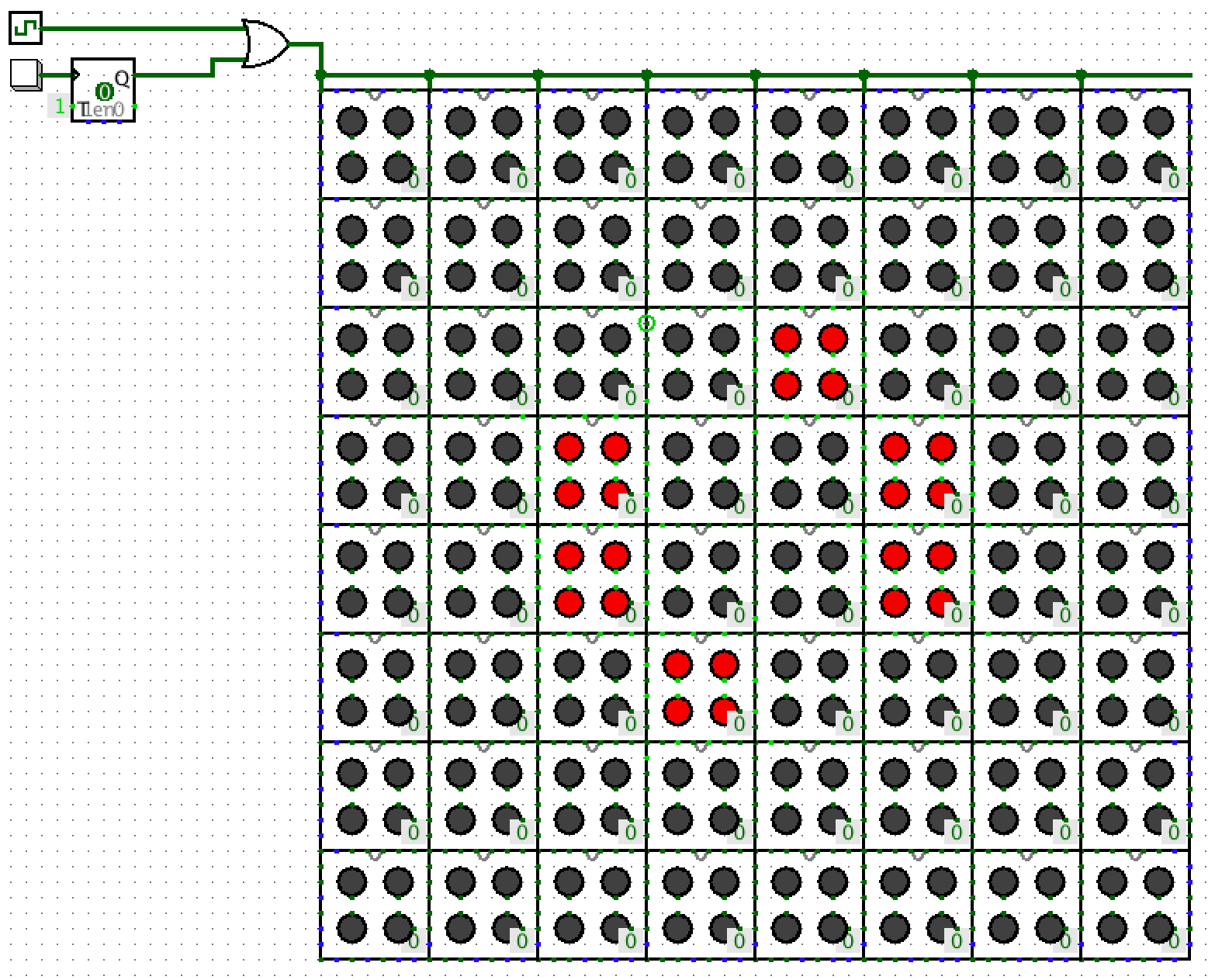
At the highest level, this screenshot shows how the main circuit looks:
Those 0s are there because I couldn't get buttons to work reliably. Sometimes clicking a button would work, sometimes Logisim would decide I wanted to select the subcircuit instead. So I replaced it with a constant that I can change the value of.
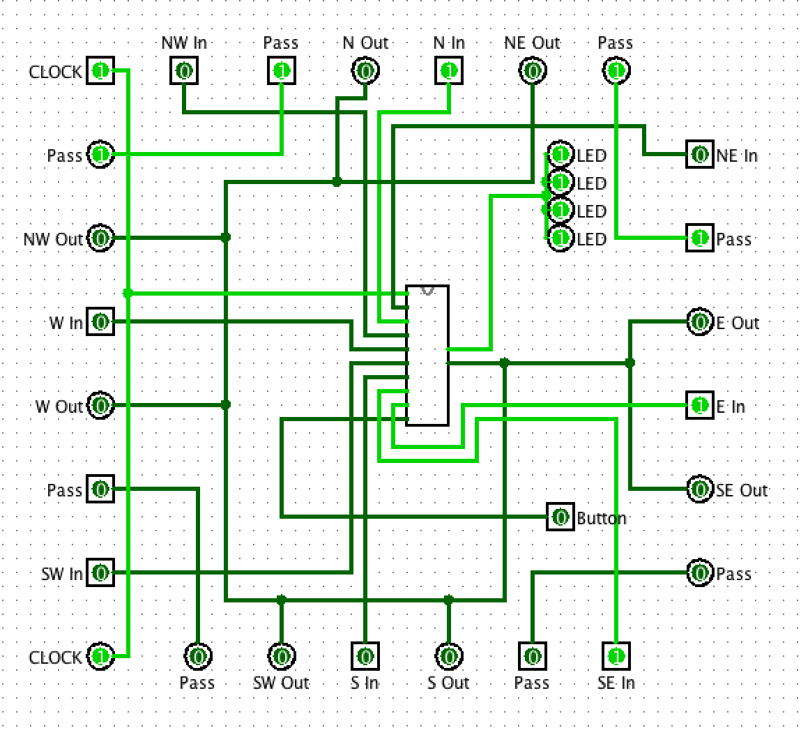
Each cell consists of a subcircuit and 4 virtual LEDs. The contents of the cell subcircuit are mainly wires that connect all the outputs to a "brain" subcircuit. The inputs and outputs are arranged in such a way that each cell can communicate with all 8 of its neighbors, as well as pass a clock signal down the columns.
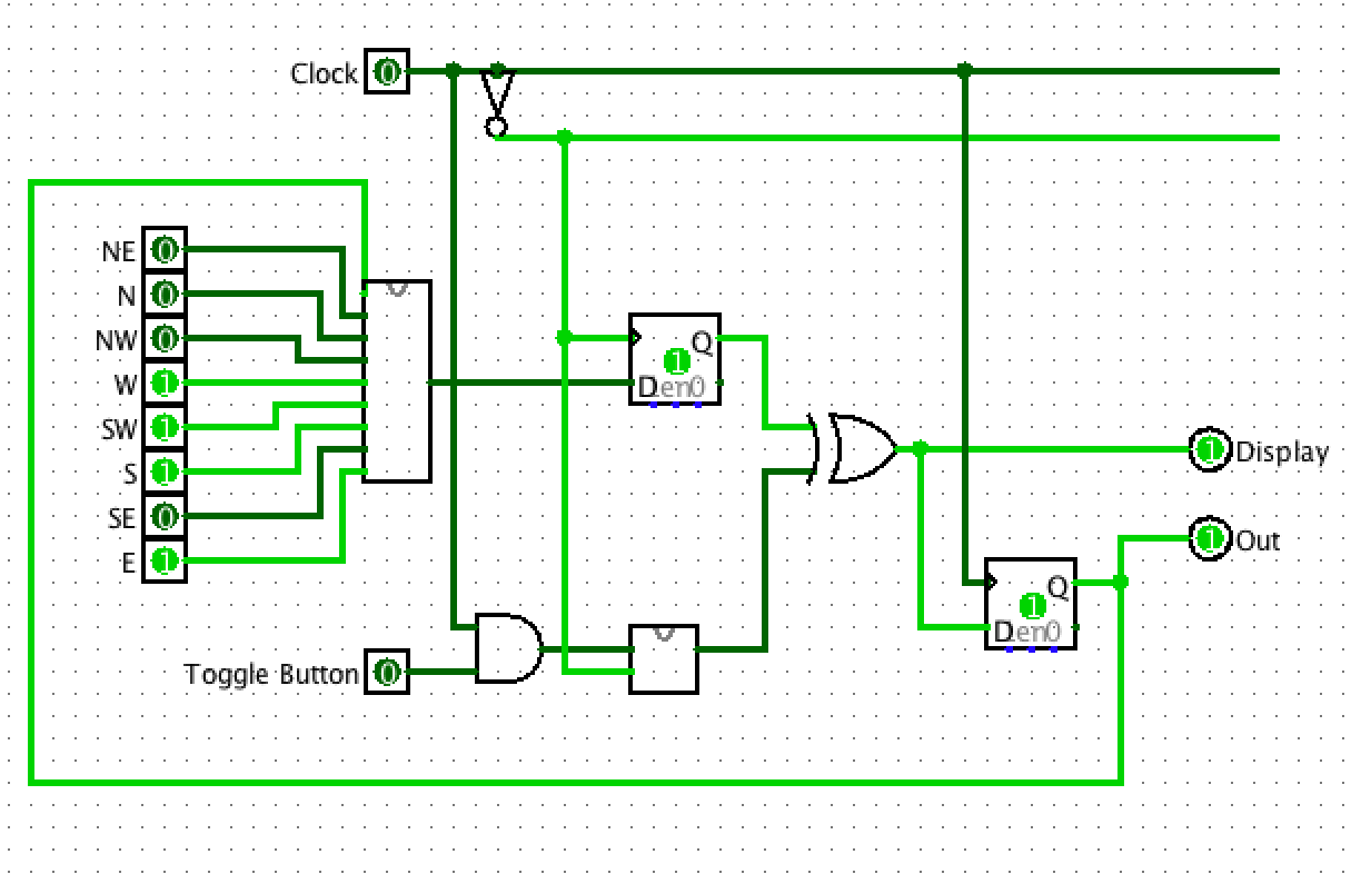
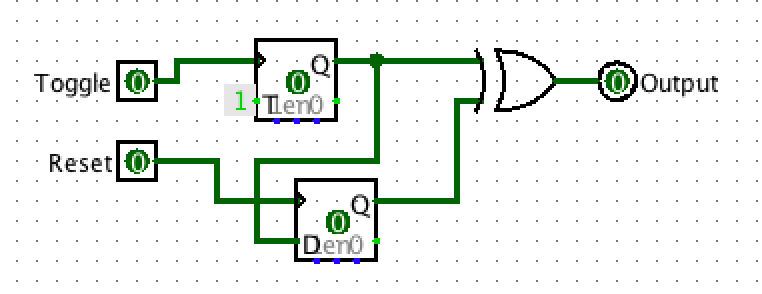
The brain circuit contains logic that keeps the cells synchronized with each other. There are two D-latches, and each is triggered by a different edge of the clock signal. When the clock rises to 1, it stores the next state for the cell and updates the LEDs, and when the clock falls to 0, it propagates the state to the neighbor cells. There is also a "resettable toggle": a simple subcircuit that allows one to toggle the current state of the cell using the button (actually the 0s), but then revert to the non-toggled state on the next update.
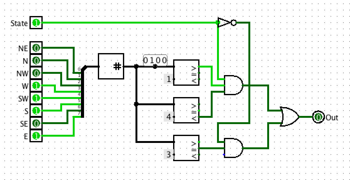
The larger circuit in the brain subcircuit is the meat of the Conway's Game of Life simulation. It uses some of Logisim's math circuits to count the number of activated numbers and determine whether or not the cell should be alive in the next clock tick.
The great thing about the modular design is that by duplicating the cells, we can increase the size of the simulation to any arbitrary size. In this case, I made an 8x8 cell grid, but any dimensions are theoretically possible. (Unless Logisim decides to crash, which it tends to do.)
For example, here's a (slightly blurry) animation of a larger simulation I ran of a glider (with additional stuff on the sides to make it wrap around). Logisim did not like this, and kept having issues with random cells when I would reopen the file, but I finally got it to work.
If you want to download the file, you can do so here.